
What is an Airfoil?
An airfoil is a specialised 2D shape that efficiently produces the maximum lift for a fluid flowing across it.
If you’ve ever seen the cross-section of a wing, you’re likely to have seen an airfoil already. An airfoil (or a hydrofoil for water) is employed in aircraft, cars, propeller blades, turbines, sailboats… you name it.
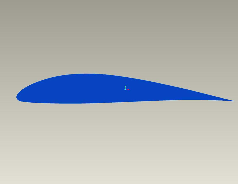
The reason for its wide usage? Its ability to produce the most lift possible of all the known shapes. Let’s see what makes this distinctive teardrop shape so special.
How does it produce lift?
Around the world, there are a few theories that try to explain the phenomenon of lift generation by an airfoil. Interestingly, there’s still debate among scientists about which theory is the most simple & intuitive. There are also a few partially erroneous theories. Let’s start with the flawed ones first.
1) Equal times theory:
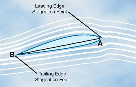
Say we have an airfoil. For simplicity, we consider the airfoil’s frame of reference, with the fluid moving past it. The incoming fluid stream first encounters the leading edge, where it splits to go over the top and bottom parts.
Both of the streams must arrive at the trailing edge at the same time. But the distance to be covered by the upper stream is larger, and so it must have a higher velocity to arrive at the same time.
According to the Bernoulli principle, a higher velocity is associated with a lower pressure. Therefore, a region of low-pressure forms above the airfoil. Similarly, the lower stream has a smaller velocity and thus a higher pressure. Hence, an area of high pressure is created below the foil. This pressure difference produces the required lift.
This theory, although quite intuitive, is partially flawed.
No rule in physics states that the upper and lower streams must arrive at the same time at the trailing edge. In reality, the upper stream arrives about 20% faster. Having a longer distance to travel does not increase the velocity of the upper stream.
If it does, the following shape must produce an exceptional amount of lift—
But it doesn’t. This theory can’t explain how planes can fly inverted.
2) Newton’s third law:
This theory uses Newton’s third law to treat air as a collection of particles. Air just bounces off the underside of the wing, the reaction force of which produces lift. Although this is true to an extent, we can’t consider air to be a bunch of small balls. Its behaviour is much more complex.
How does it really work?
There are mainly 2 schools of thought around fluid flow. One—known as the inviscid fluid flow theory— ignores the viscosity effects of air to explain lift generation. It uses potential flow, and circulation concepts with the Kutta-Joukowski theorem to explain lift.
The other theory takes into account the viscous nature of air. As the airfoil moves through a fluid stream, the point that first encounters the fluid is known as the stagnation point. Here, the velocity of fluid becomes 0, and this point splits the fluid stream to go over the upper and lower contours. The air flowing over the upper surface accelerates and has to travel faster than the air below. A faster fluid is associated with a lower pressure, and vice-versa from the Bernoulli principle. This produces a pressure difference, which causes lift.
Further, the incoming airstream is purely horizontal which is deflected downwards after encountering the airfoil. This is due to the airfoil pushing down on the air and from Newton’s third law, the air pushes back on the airfoil. A combination of these two factors produces lift as we know it.
A caveat is that air tends to follow the airfoil surface until the trailing edge rather than just moving off tangentially. This is due to the Coandă effect which describes a fluid’s tendency to follow a curved surface due to pressure differences caused by streamlined curvature.
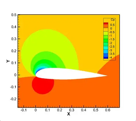
Understanding Pressure Distribution
The key to understanding lift lies in how pressure varies around the airfoil surface. As air flows over the curved upper surface, it accelerates and creates a region of lower pressure. Simultaneously, the air moving under the airfoil experiences less acceleration, maintaining higher pressure.
This pressure distribution isn’t uniform. It varies continuously from leading to trailing edge. The pressure is lowest at the point of maximum curvature on the upper surface and gradually recovers towards the trailing edge. This pressure map is what CFD analysis seeks to capture, as it directly determines the forces acting on the airfoil.
Parts of an Airfoil
To describe the shape of an airfoil accurately, it is important to understand the different terminologies associated with it.
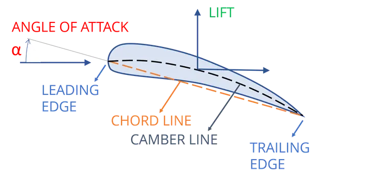
The leading edge is the forwardmost edge of an airfoil, which makes the first contact with the fluid stream.
The trailing edge is at the rear of the airfoil. It is where the upper and lower contours meet.
A straight line from the trailing edge to the leading edge is known as the Chord Line.
The angle made by the chord line with the incoming airflow is said to be the angle of attack. A higher angle of attack generates more lift for the same velocity. The lift increases up to the stall point, beyond which it decreases sharply. If an aircraft tries to take off too aggressively, it might stall.
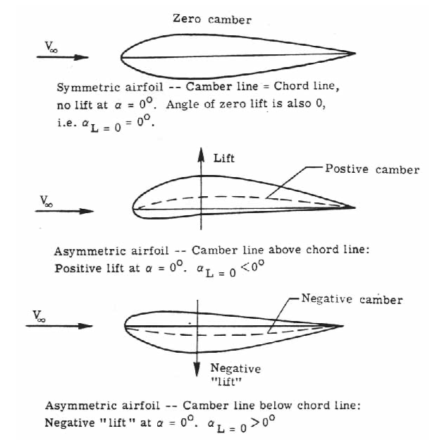
A line equidistant from the upper and lower contours is known as the camber line. The maximum distance of the camber line from the chord line gives the camber. It’s a measure of the asymmetricity of the airfoil. It is usually expressed as a percentage of the chord length.
Depending on the camber, airfoils are categorised into 3 types:
-
Positive cambered airfoils are characterised by their ability to produce lift even at a 0° angle of attack. They are the most common types of airfoils & found in aeroplanes and bird wings.
-
Symmetric airfoils (or 0 camber airfoils) are airfoils with their chord line coinciding with their camber line. They produce no lift at 0° angle of attack and are commonly employed in stunt planes that fly inverted.
-
Negative cambered airfoils have the camber line below their chord line. They produce a “negative” lift and are employed in Formula cars for downforce that offers better traction and handling.
Varying each of these parameters, hundreds of variations of airfoils can be made. Each airfoil might be suited for a particular flight regime. Modern aircraft use different airfoils along the cross-section of the wing from root to wingtip, with a gradual transition in between. They are also equipped with slats (leading edge) and flaps (trailing edge) which optimise the airfoil shape for different flight regimes. During takeoff, a high amount of lift is needed, so flaps are extended. But this increases drag, so flaps are retracted during the cruise phase to maximise fuel efficiency.
The Boundary Layer and Flow Separation
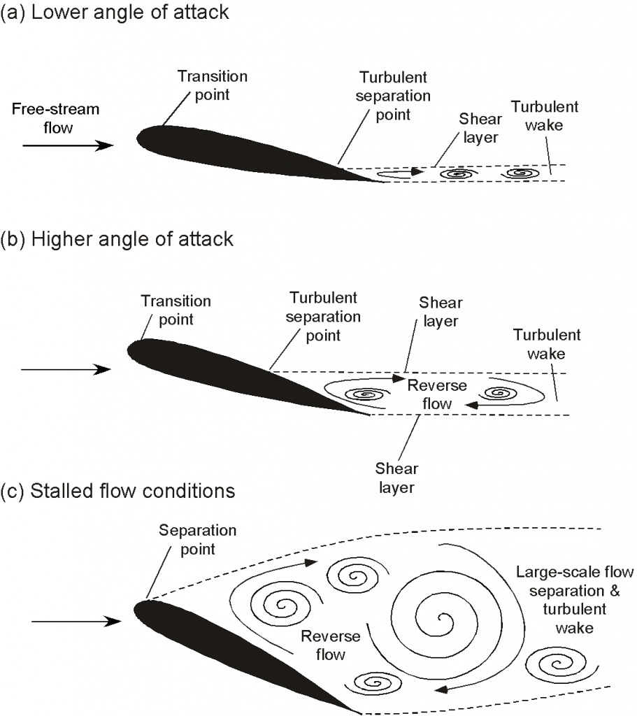
When air flows over any surface, including an airfoil, the layer of air immediately adjacent to the surface sticks to it due to viscosity. This creates a boundary layer—a thin region where the air velocity gradually increases from zero at the surface to the free stream velocity.
What causes flow separation?
As the boundary layer moves along the airfoil surface, it encounters regions where pressure increases in the direction of flow—this is called an adverse pressure gradient. Think of it like air trying to flow uphill in terms of pressure. The air in the boundary layer, already slowed down by friction, doesn’t have enough energy to overcome this pressure rise. When this happens, the flow can no longer follow the airfoil surface and separates. Instead of sticking to the surface, the air breaks away, creating a turbulent wake behind the airfoil.
The stall phenomenon
Flow separation is directly related to stall. As the angle of attack increases, the adverse pressure gradient on the upper surface becomes stronger. Eventually, the boundary layer separates near the leading edge, causing a drastic loss of lift and increase in drag. This is why pilots must be careful not to exceed the stall angle, especially during takeoff and landing.
The stall angle typically occurs around 15-20° for most airfoils, though this varies with airfoil design and flight conditions.
The 4 fundamental forces
In aerodynamics, there are 4 fundamental forces: Lift, Weight, Thrust and Drag. Lift balances weight, and thrust balances drag. When an object produces more lift than its weight, it can take flight. An intricate balance between these 4 forces gives us controlled flight.
The pressure around an airfoil varies continuously from leading to trailing edge. Understanding this pressure distribution is crucial for CFD analysis, as it directly relates to the forces generated and helps identify potential flow separation points. We will cover more about flow separation in upcoming posts.
Flow separation significantly impacts this force balance. When an airfoil stalls due to flow separation, lift drops dramatically while drag increases sharply. This is why understanding boundary layer behavior is crucial for safe aircraft operation—it directly affects the balance between these fundamental forces. The wake created by flow separation also affects aircraft behind it, which is why air traffic control maintains spacing between aircraft, especially during takeoff and landing when they operate closer to stall conditions.
NACA Airfoils
The National Advisory Committee for Aeronautics (NACA) was established in 1915 to address the United States’ deficiency in aeronautical research. They developed a system of standardised airfoil geometries which are encoded in a 4-digit system.
This 4-digit system uniquely encapsulates the airfoil geometry through 4 digits:
- First Digit: Denotes maximum camber as a percentage of chord length. E.g., In the NACA 2415 airfoil, “2” denotes a 2% camber relative to the chord length.
- Second Digit: Position of maximum camber from the leading edge, expressed in tenths of the chord. E.g., For NACA 2415, “4” denotes the maximum camber at 40% of the chord.
- Third and Fourth Digits: Maximum thickness as a percentage of the chord length. In NACA 2415, “15” signifies a 15% thickness-to-chord ratio.
Examples:
- NACA 0006: A symmetrical airfoil with 0% camber and 6% thickness, used in helicopter rotors and stabilizers for neutral lift at zero angle of attack
- NACA 2415: A cambered airfoil (2% camber at 40% chord) with 15% thickness, employed in general aviation wings for balanced lift and structural robustness
- NACA 4412: Features 4% camber at 40% chord and 12% thickness, common in low-speed aircraft due to high lift characteristics
This system allows engineers to quickly select airfoils tailored to specific performance criteria, such as maximizing lift or minimizing drag, without requiring physical prototyping. We’ll be simulating fluid flow across the 4-digit airfoils in upcoming posts.
Quantitative Performance Metrics
The performance of an airfoil is quantitatively measured through 3 dimensionless quantities:
Lift Coefficient (\(C_l\)):
In Aerodynamics, we typically deal with “Lift Coefficient” rather than “Lift”. It’s defined as:
$$C_l = \frac{L}{\frac{1}{2}\rho v^2 c}$$Where:
- \(L\) = Lift force
- \(\rho\) = Fluid density
- \(v\) = Velocity
- \(c\) = Chord length
A \(C_l\) of 1.2 at a 10° angle of attack is considered efficient lift generation.
Drag Coefficient (\(C_d\)):
Similarly, the Drag Coefficient is defined as:
$$C_d = \frac{D}{\frac{1}{2}\rho v^2 c}$$Where \(D\) is the drag force. A low \(C_d \approx 0.02\) signifies minimal air resistance.
Since we’re dividing by the velocity & chord length, these quantities are more generalised & non-dimentionalised than the actual forces, allowing airfoils with different shapes and sizes to be compared.
Lift to Drag ratio (L/D):
The Lift to Drag ratio compares lift generated to drag incurred:
$$\frac{L}{D} = \frac{C_l}{C_d}$$Higher L/D values allow for extended glide ranges (\(\sim\)50:1 for gliders) while fighter jets tend to keep it low for increased manoeuvrability.
Reynolds Number
Reynolds Number is fundamentally responsible for how an airfoil behaves. It’s calculated as:
$$Re = \frac{\rho V L}{\mu}$$Where:
- \(\rho\) = Fluid density
- \(V\) = Velocity
- \(L\) = Characteristic length (chord length here)
- \(\mu\) = Dynamic viscosity
But what does this really mean?
At low Reynolds numbers (Re < 100,000), like those experienced by model aircraft or insects, viscous forces dominate. The boundary layer is thick relative to the airfoil size, and flow separation occurs easily. This is why paper airplanes stall at lower angles of attack and why insects need to flap their wings differently than birds.
At high Reynolds numbers (Re > 1,000,000), typical for commercial aircraft, inertial forces dominate. The boundary layer is relatively thin, and the flow can follow the airfoil surface more effectively before separating. This allows for higher angles of attack before stall and generally better aerodynamic performance. The transition between these regimes significantly affects:
- Stall characteristics: Low Re airfoils stall more gently but at lower angles
- Drag levels: High Re flows typically have lower drag coefficients
- Lift generation: The maximum lift coefficient changes with Reynolds number
This is why wind tunnel testing must account for Reynolds number scaling, and why the same airfoil design performs differently on a drone versus a commercial airliner.
Additional Resources
For further exploration of airfoil theory and applications:
Videos & Online Tools:
- Lift and Wings - Sixty Symbols
- How Airplane Wings REALLY Generate Lift
- How do Wings generate LIFT?
- Mastering Airfoil Selection for Drones - Part 1: Theory
- Understanding Aerodynamic Lift
- NACA Airfoil Generator - Interactive airfoil coordinate generation. We’ll be using this in our simulations in later posts.
Conclusion
Airfoils are fascinating structures that play a crucial role in the world of aerodynamics. From their unique shapes to their ability to generate lift, they are integral to every machine operating in fluids. Understanding the principles behind airfoil design and performance is essential for anyone interested in aerodynamics or aerospace engineering.
That’s it for this post! If you’ve made it this far, give yourself a pat on the back, ‘cause it’s all downhill from now! The real fun is about to begin!